Methodological Overview & Pedagogical Purpose
Beginner designers often assume digital CAD dimensions translate into identical physical shapes immediately after fabrication. Thermal shrinkage in plastic, molten filament bulge at layer boundaries, and mechanical backlash cause parts modeled with identical dimensions to fuse tightly together. Addressing this gap requires establishing intentional clearance offsets before sending geometry to the printer.
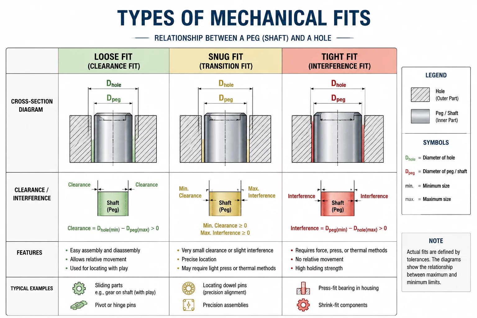
This reference document categorizes tolerance boundaries into functional mechanical tiers. Students examine how standard FDM desktop printers handle intentional gaps between 0.1 mm and 0.8 mm. By linking nominal dimensions with mechanical fit requirements, learners anticipate fabrication variance and develop realistic prototyping habits.
Instructor Core Recommendation
Always instruct students to print a small 2-minute calibration test coupon before manufacturing large multi-part assemblies. Verifying the specific nozzle extrusion width saves hours of print time and prevents wasted plastic filament.
Dimensional Framework & Step-by-Step Instructions
Implement mechanical fits methodically across student design projects using four standard tolerance zones:
- Tight Press Fit (0.1 mm - 0.2 mm offset): Ideal for permanent joinery, peg caps, and dowel pins that stay locked without adhesive.
- Snug Friction Fit (0.25 mm - 0.35 mm offset): Best for removable lids, slotted organizers, and swappable tool bits that stay secure under light handling.
- Free Sliding Motion (0.4 mm - 0.55 mm offset): Required for drawer runners, rotating axles, and telescoping arms that need smooth movement without binding.
- Loose Clearance Joint (0.6 mm - 0.8 mm offset): Recommended for print-in-place hinges, dynamic chain links, and loose container latches where bridge sagging occurs.
Apply offsets symmetrically across mating surfaces. When designing an internal shaft inside an outer bore, deduct half of the total tolerance value from the shaft perimeter while expanding the internal bore perimeter by the matching remainder.
Formative Assessment Rubric & Fit Verification
Evaluate physical student prototypes using functional hands-on benchmarks rather than visual inspection alone:
- Interference Verification: Examine whether parts assemble by hand without requiring hammer strikes, razor scraping, or sanding operations.
- Gravitational Retention: Invert assemblies with friction-fit lids to check if gravity alone causes components to disconnect unexpectedly.
- Rotational Independence: Rotate moving joints through a continuous 360-degree cycle to confirm absence of friction binding points.
Documenting deviation between CAD models and finished prints teaches students to calibrate their software parameters systematically against real-world manufacturing constraints.
Marcus Vance
STEM EducatorThis guide resolved our students' constant issue with fused hinge joints. Accounting for the 0.4mm nozzle expansion was the breakthrough our classroom needed.