Methodological Overview & Pedagogical Purpose
In introductory 3D modeling and additive manufacturing courses, students frequently struggle with the gap between nominal CAD dimensions and real-world physical behavior. When novice designers construct interlocking components such as interlocking box lids, shaft couplings, or hinge pins, they commonly specify zero clearance. The resulting printed parts inevitably bind or refuse to assemble due to standard thermoplastic expansion, extruder nozzle pressure variations, and perimeter layer stepping.
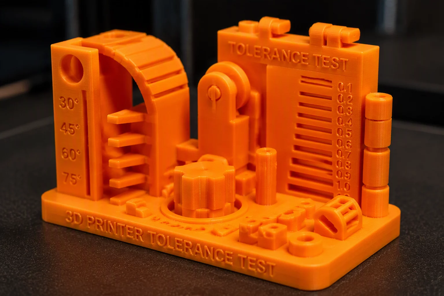
The 3D Printing Fit Test provides educators with a reproducible laboratory protocol designed to calibrate machine-specific tolerances before committing to larger, multi-hour student builds. By investigating mechanical fit through standardized incremental test specimens, learners transition from trial-and-error guesswork to genuine empirical engineering analysis. They systematically examine how wall line count, printing temperature, layer height, and material shrinkage affect precision mating surfaces.
Instructor Core Recommendation
Always mandate that students run tolerance test coupons using the exact layer thickness, print orientation, and filament spool planned for final mechanism fabrication. Changing from a 0.20 mm standard profile to a 0.28 mm draft profile alters bead expansion and can render a verified 0.2 mm clearance non-functional.
Dimensional Framework & Step-by-Step Instructions
Execute this diagnostic procedure across four structured classroom phases to cultivate practical measurement habits and design compensation skills:
- Phase 1: Measure baseline printer accuracy across X, Y, and Z axes using digital calipers on standard 20 mm calibration test cubes to identify linear drift.
- Phase 2: Construct a multi-gauge stepping card in CAD featuring cylindrical pegs ranging from 5.0 mm to 10.0 mm alongside receiving sockets with radial clearances of 0.1 mm, 0.2 mm, 0.3 mm, 0.4 mm, and 0.5 mm.
- Phase 3: Orient test coupons vertically on the build platform to assess anisotropic layer cohesion and seam corner bulging under classroom slicer profiles.
- Phase 4: Manually test push-fit insertion, sliding movement, and free rotation across each pairing, recording quantitative engagement force on individual tracking sheets.
Following the assembly check, students determine the baseline clearance threshold for their designated mechanical joint. On standard classroom FDM 3D printers, sliding friction joints typically require an overall diametral clearance of 0.30 mm to 0.40 mm, whereas static press-fit components operate reliably with 0.15 mm to 0.20 mm of offset allowance.
Formative Assessment Rubric & Fit Verification
Assess student mastery and diagnostic competence using this tiered evaluation standard:
- Dimensional Data Integrity: Accurately records nominal digital CAD measurements versus caliper-measured physical parts within 0.05 mm precision.
- Fit Function Categorization: Correctly classifies mechanical interfaces into interference, transition, and running clearance categories according to project requirements.
- Iterative CAD Rectification: Applies calculated radial offsets back into original 3D models before starting the final full-scale production print.
Implementing this diagnostic step into the early stages of design projects reduces filament waste, minimizes repetitive print failures, and instills rigorous industrial tolerances in young makers.
No comments yet. Be the first to share your classroom experience or teaching insights.