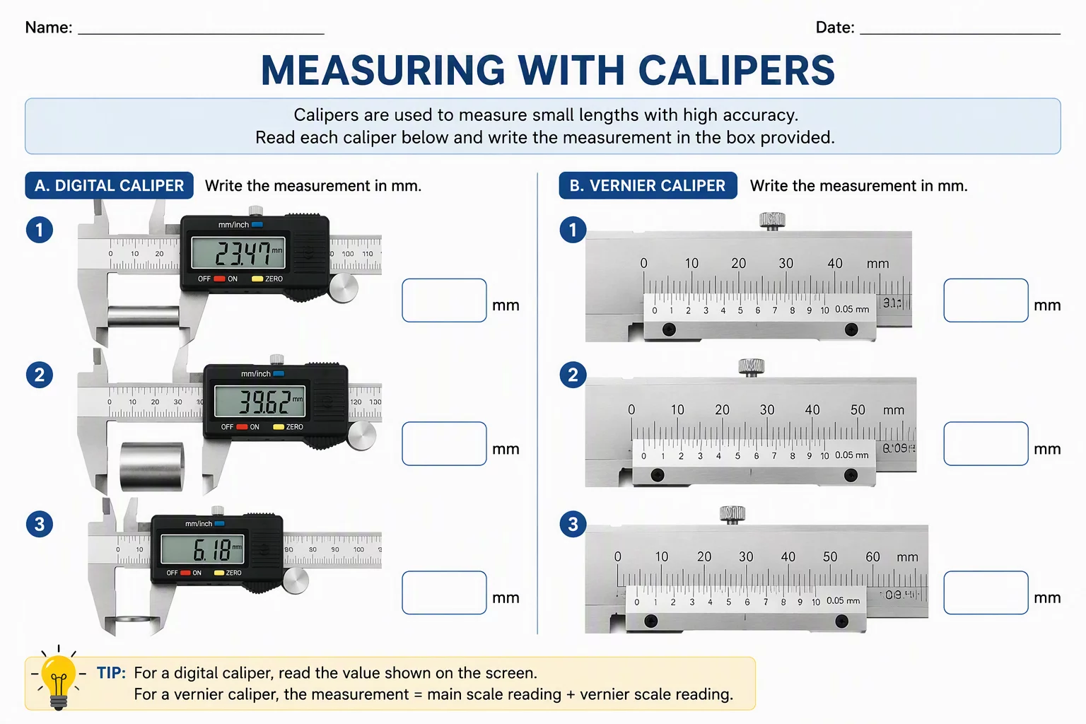
Methodological Overview & Pedagogical Purpose
Precision measurement bridges theoretical 3D computer-aided modeling and physical manufacturing realities. Beginners frequently design 3D parts using estimated dimensions or standard visual rulers, which reliably causes print fitment failures and material waste. This worksheet guides students systematically through high-accuracy measurement techniques using digital and mechanical vernier calipers.
Students work in pairs to inspect standardized classroom artifacts such as cylindrical dowels, stepped bushings, bolt threads, and molded rectangular cases. The worksheet reinforces the conversion of millimeter readings into parameterized design constraints, instilling an intuitive appreciation for zero-point calibration and repetitive measurement consistency.
Instructor Core Recommendation
Always instruct learners to wipe caliper contact jaws clean and confirm the zero-point reading before clamping every test specimen. Uneven jaw pressure or trapped dust particles can skew dimensional readings by up to 0.3 millimeters.
Dimensional Framework & Step-by-Step Instructions
Follow these progressive stages to complete the caliper measurement drill during a standard 45-minute laboratory session:
- Zero Calibration: Close the main jaws fully, inspect for light gaps between mating surfaces, and press the digital zero button or note the vernier alignment zero mark.
- Outside Dimension Recording: Position the thickest section of the test object between the large external jaws, apply gentle thumb-wheel contact, and record the value across three distinct points to detect taper.
- Internal Bore Verification: Insert the upper internal jaws into the object cavity, spread the slide smoothly until contact is established, and capture the maximum stable diameter.
- Depth and Step Gauging: Extend the slender depth probe or utilize the stepped base reference face against flat edges to measure cavity depth and shoulder heights with perpendicular alignment.
After capturing raw measurements, learners record each value into the provided worksheet grid, calculate the arithmetic mean of their triplicate readings, and flag any dimensional variation exceeding 0.1 millimeters.
Formative Assessment Rubric & Fit Verification
Evaluate student readiness before advancing to full-scale digital CAD extrusion and 3D printing tasks:
- Tool Handling Accuracy: Demonstrates perpendicular jaw placement without twisting delicate objects or applying excessive clamping force.
- Data Consistency: Records three repeatable measurements within ±0.05 mm variance for rigid materials on the lab worksheet.
- CAD Parameter Translation: Accurately transfers physical caliper readings into 3D software shape dimensions, accounting for designated wall tolerances.
Completing this worksheet eliminates common dimensional mistakes, equipping students with industrial metrology habits that carry over directly into rapid prototyping projects.
No comments yet. Be the first to share your classroom insights or teaching notes!