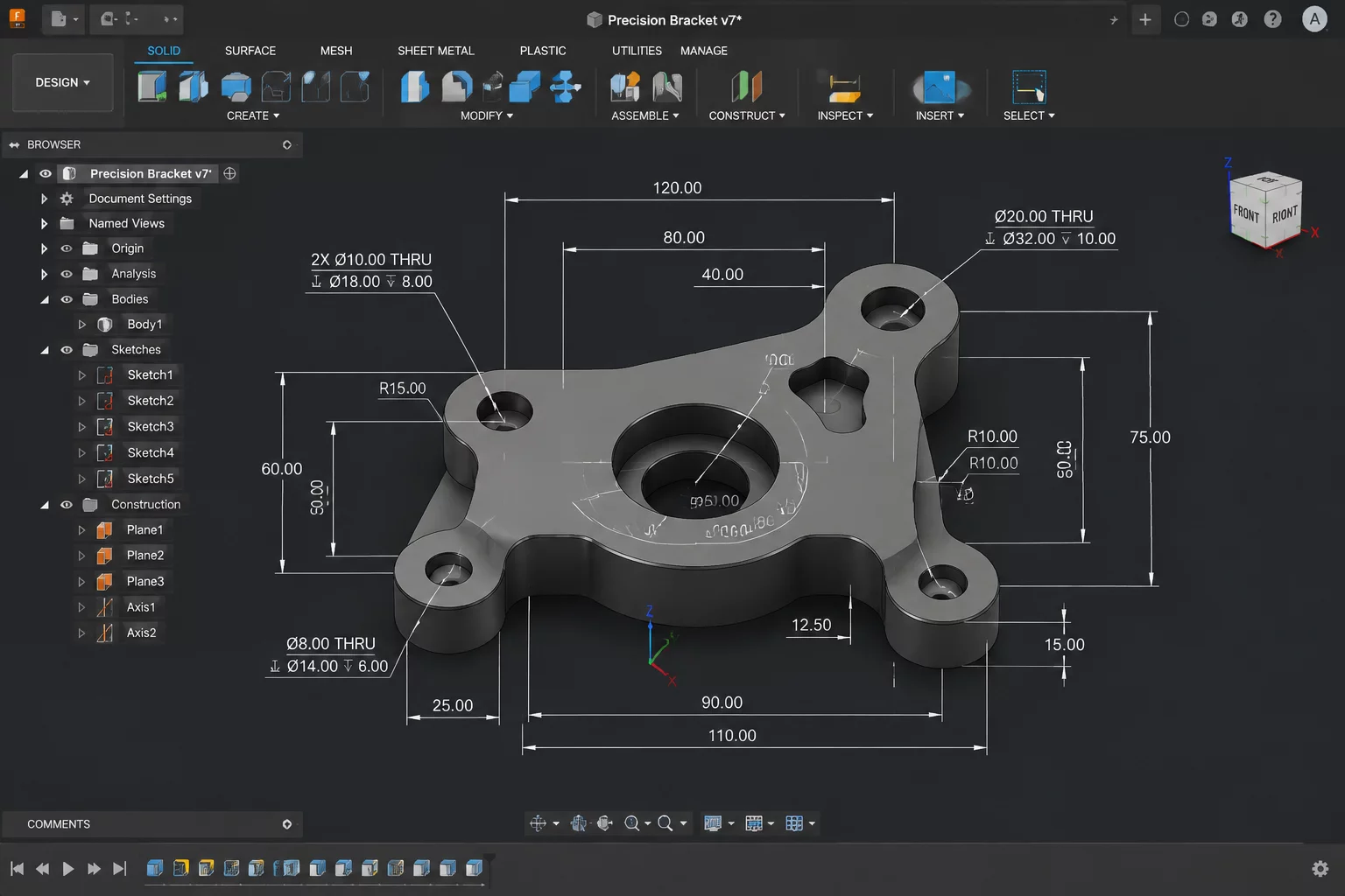
Classroom Scale & Dimension Objectives
In introductory CAD learning environments, students frequently manipulate geometric shapes solely by dragging mouse handles across the screen. While intuitive, this habit inevitably results in arbitrary non-standard dimensions that fail to mate with real-world hardware. When students attempt to print functional enclosures, holders, or interlocking joints, the lack of intentional millimeter control causes assembly failures and wasted classroom filament.
Establishing dimensional mastery requires students to treat Tinkercad not as a digital clay studio, but as an engineering CAD tool. By pairing caliper measurements with direct numerical typing, students discover that precise coordinate entry, grid alignment, and intentional clearance offsets guarantee reproducible physical objects on the 3D printer bed.
Proportion & Measurement Rule
Always input explicit numerical millimeter values rather than dragging shape handles by hand. Account for a minimum of 0.3 mm to 0.5 mm radial clearance on all interlocking 3D-printed mating components.
Step-by-Step Educational Workflow
The following three-stage pipeline guides learners from tactile hardware inspection through parametric layout and final clearance verification before exporting STL files.
Stage 1: Physical Reference Measurement
Distribute physical reference items such as standard batteries, wooden dowels, or USB drives. Have students measure width, depth, and thickness using digital calipers, recording both primary dimensions and chamfer radii on a dedicated measurement worksheet.
Stage 2: Translating Values into Tinkercad
Instruct students to place the Tinkercad Ruler tool onto the workplane corner and adjust the snap grid down to 0.1 mm. Rather than resizing objects manually, students click the numeric dimension readout boxes and directly type the exact measured millimeters.
Stage 3: Testing Tolerances & Clearances
Before joining solid and hole geometries, learners calculate and add a 0.4 mm diametrical clearance buffer. They align axes using the Align tool, cross-section the model with a transparent viewing box, and check wall thickness against printer nozzle limits.
Formulas and Spatial Checks
Preventing assembly binding is achieved through systematic geometric formulas rather than guesswork. Applying standardized offsets ensures that shrinkage and layer squish do not fuse separate parts together.
- Snap grid adjusted to 0.1 mm precision before aligning critical hole locations.
- Calculated tolerance clearance of at least 0.4 mm applied to internal receptacle cavities.
- Outer wall thickness verified to exceed 1.6 mm for sufficient structural rigidity.
Once students establish these dimension verification habits, their confidence in design iterations increases significantly. They spend less time troubleshooting failed physical fits and more time exploring sophisticated mechanical assemblies that perform flawlessly straight off the build plate.
No comments yet. Be the first to leave a comment.