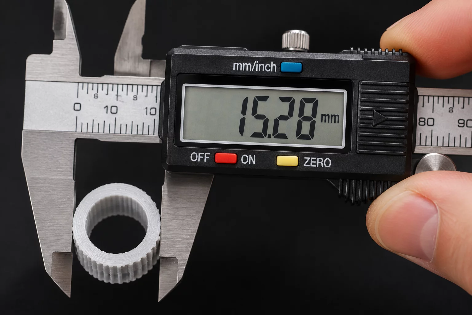
Classroom Scale & Dimension Objectives
Engineering begins when arbitrary visual sizing gives way to verifiable units. Students frequently rely on screen zoom levels to evaluate model sizes, resulting in printed objects that turn out either excessively large or too loose for assembly. Precision measurement introduces systematic methods for transferring real-world physical boundaries directly into CAD modeling coordinates.
Learners handle digital calipers to measure exterior widths, interior diameters, and stepped depths on standard physical hardware. Recording these numbers directly on paper before manipulating virtual 3D primitives enforces spatial awareness and eliminates the frustration of trial-and-error manufacturing.
Proportion & Measurement Rule
Always zero digital calipers before measuring, and add a mandatory 0.2mm to 0.4mm radial clearance offset to account for thermoplastic extrusion spread.
Step-by-Step Educational Workflow
This exercise guides classrooms through a structured three-phase pathway that transitions from physical tactile verification to digital entry and final physical tolerance fit.
Stage 1: Physical Reference Measurement
Clean the caliper jaws and zero the digital display. Measure three distinct points on the reference component: outer envelope thickness, inner hole diameter using top knife edges, and depth steps with the rear extension probe. Write every value down in millimeters with two decimal places.
Stage 2: Translating Values into Tinkercad
Place the Ruler tool directly on the Tinkercad workspace origin. Switch the grid snap resolution from 1.0mm to 0.1mm. Enter exact recorded caliper figures numerically into the dimension boxes rather than dragging corner handles freely across the screen.
Stage 3: Testing Tolerances & Clearances
Apply purposeful manufacturing clearances into female cutouts. For snug slip fits, enlarge cavity diameters by 0.3mm; for loose hinges or sliding parts, set allowances to 0.5mm. Settle on a quick 10-minute test ring print to confirm mechanical engagement before starting full-scale model production.
Formulas and Spatial Checks
Understanding why parts fit or fail requires mastering the basic relationship between nominal size and manufactured clearance:
- Hole Cutout Dimension = Measured Object Outer Diameter + (2 × Desired Clearance)
- Verify wall thickness remains at least three times nozzle diameter (1.2mm minimum for 0.4mm nozzles)
- Perform cross-section clipping checks in slicer software to confirm zero overlap on moving subassemblies
When students develop the instinct to measure twice and calibrate their CAD workplanes before designing decorative features, print failure rates drop drastically. This disciplined habit builds strong analytical thinking that serves learners across STEM disciplines, industrial product design, and architectural modeling.
No comments yet. Be the first to leave a reflection on this lesson!