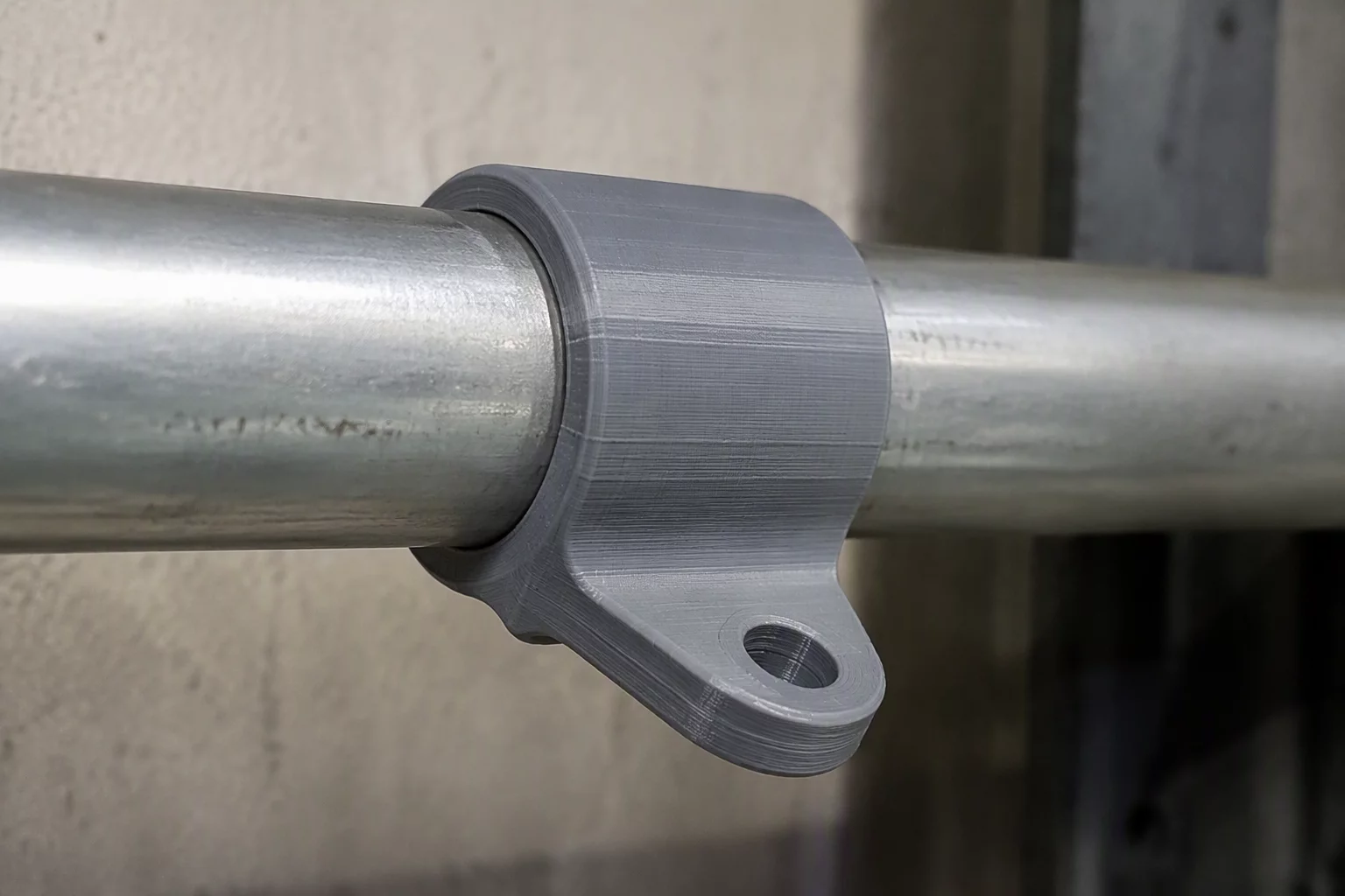
Classroom Scale & Dimension Objectives
Beginner designers often spend extensive classroom time adding intricate surface details, beveled trims, embossed text, and bright color schemes before verifying whether their model physically mates with real-world objects. When the print completes four hours later, the inner socket proves too tight by a fraction of a millimeter. Every minute invested in surface ornamentation is wasted when the fundamental geometry fails its primary mechanical purpose.
This lesson instills an engineering-first habit called minimal viable fit testing. Students isolate the mounting socket, sleeve, or snap joint as a minimalist test geometry. They verify mechanical tolerance through quick draft prints before investing creative energy into final visual aesthetics.
Proportion & Measurement Rule
Always add radial offset allowance (0.2 mm to 0.4 mm for standard FDM printing) to mating components before locking in outer decorative geometry.
Step-by-Step Educational Workflow
Structure the classroom activity around three distinct design checkpoints. Each stage requires physical verification before students obtain permission to open cosmetic modeling tools.
Stage 1: Physical Reference Measurement
Measure the target object across three points with a digital caliper. Record inner and outer diameters on the worksheet to identify real manufacturing variations in the reference item.
Stage 2: Translating Values into Tinkercad
Create a plain primitive cylinder or box hollow with a 0.3 mm clearance gap. Strip away all unnecessary chamfers, fillets, and decorative extrusions to keep slicer preview times under two minutes.
Stage 3: Testing Tolerances & Clearances
Slice and print only the 5 mm tall gauge ring. Test the physical fit directly on the target object. Once sliding friction meets the project rubric, merge the verified dimensions into the decorative model.
Formulas and Spatial Checks
To prevent loose parts or binding joints, instruct learners to evaluate their internal dimensions against standard filament shrinkage and nozzle expansion formulas before starting 3D render previews.
- Verify internal hole diameter equals measured object diameter plus 0.4 mm total clearance.
- Confirm minimum wall thickness remains at least 1.6 mm (4 nozzle perimeters) around the mating cavity.
- Run a 10-minute calibration ring print before assembling complex multi-part visual elements.
Encouraging this systematic habit transforms how students approach engineering challenges. When learners understand that mechanical accuracy guarantees a usable creation, aesthetic styling becomes an exciting reward rather than a source of frustration.
David Miller
FabLab CoordinatorPrinting rapid 5 mm test collars completely eliminated our classroom filament waste. Students now refuse to add chamfers or textures until their caliper test ring clicks cleanly into position.