Classroom Scale & Dimension Objectives
In digital modeling environments, shapes expand or contract without resistance. Students often place geometric primitives on the screen assuming that a thirty-millimeter cylinder will seamlessly fit into a thirty-millimeter hole in real life. When fabricated parts arrive from the 3D printer, real physical constraints such as thermal contraction, filament expansion, and nozzle path tolerances quickly reveal discrepancies between expectation and physical reality.
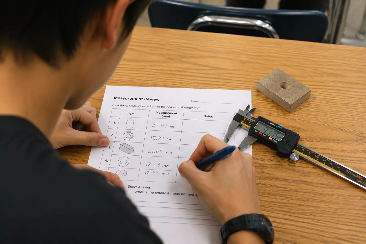
The Dimension Reflection activity provides a structured feedback loop where students systematically measure manufactured test prints against their original digital blueprints. Instead of treating unexpected loose or tight fits as failures, learners document numerical variances along the X, Y, and Z axes. This process develops critical spatial intuition and transforms abstract millimeter inputs into concrete geometric comprehension.
Proportion & Measurement Rule
A digital millimeter represents absolute geometry, while a physical millimeter accounts for material flow and machine tolerance. Always calculate an intentional offset of 0.2mm to 0.4mm for interlocking assemblies.
Step-by-Step Educational Workflow
Guide your class through the three reflection phases below. Students record their planned dimensions, perform tool calibration, and compute deviation percentages directly into their laboratory worksheets.
Stage 1: Physical Reference Measurement
Students zero their digital calipers, measure the fabricated calibration cube along width, depth, and height, and log the numbers into column one of the reflection worksheet.
Stage 2: Translating Values into Tinkercad
Learners reopen their 3D CAD project files, verify the exact numerical fields assigned to each component, and calculate the mathematical delta between software dimensions and physical caliper readouts.
Stage 3: Testing Tolerances & Clearances
Assemble the mating components. If friction prevents smooth engagement, apply an offset clearance of 0.3mm to inner slots before initiating subsequent print iterations.
Formulas and Spatial Checks
Before finalizing revisions inside the CAD editor, students run their numbers through standard engineering validation checkpoints to guarantee consistent dimensional behavior across diverse printer beds:
- Calculate axis variance: subtract measured physical value from nominal digital value.
- Confirm minimum wall thickness exceeds three times the nozzle diameter (1.2mm minimum).
- Verify internal hole compensation to prevent cylindrical shrinkage along the horizontal layer lines.
By incorporating structured reflection into every design challenge, young designers build lifelong analytical reasoning, learning to approach dimensional errors with curiosity, precision, and methodical problem-solving.
David Miller
Middle School STEM EducatorUsing this dimension reflection worksheet completely altered how my eighth-graders think about 3D models. Instead of blindly hitting re-print, they now pause, measure with calipers, and adjust their hole offsets mathematically.